4

Main Pipe in AirConditioner:VariableRefrigerantFlow:FluidTemperatureControl

I am a confused by the term Main Pipe in the AirConditioner:VariableRefrigerantFlow:FluidTemperatureControl object. In particular by the field Diameter of Main Pipe Connecting Outdoor Unit to Indoor Units. Is the main pipe supposed to include the piping from the outdoor air unit to the branch controller and to the indoor unit?

As far as I know the pipe diameter between each element (outdoor air unit, branch controller and indoor unit) is not necessarily the same and some manufacturers seem to refer to the piping between the the outdoor air unit and the branch controller only as the main pipe (example, Table 8, page 21).

Jeremy's avatar
1.6k
Jeremy
asked 2017-08-21 18:08:38 -0500
edit flag offensive 0 remove flag close merge delete

Comments

add a comment see more comments

2 Answers

3

I've checked with the some of the developers of the model (Rongpeng Zhang and Kaiyu Sun).

The "main pipe" refers to the pipe connecting the outdoor unit to the first branch joint.

Jeremy's avatar
1.6k
Jeremy
answered 2017-08-24 11:59:12 -0500
edit flag offensive 0 remove flag delete link

Comments

Let's put that in the documentation please! Can you open an issue on github? (or better, do the changes an open a pull request instead... :))

Julien Marrec's avatar Julien Marrec (2017-08-25 02:31:01 -0500) edit

@Julien Marrec, sure! I'll take care of it.

Jeremy's avatar Jeremy (2017-08-25 19:18:29 -0500) edit
add a comment see more comments
3

I'll let more knowledgeable people chime in, because I'm a bit confused too.

I think this includes all piping from the outdoor unit to the indoor unit itself. It's used to calculate both the heat loss and pressure drop.

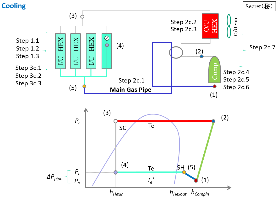
See Engineering Reference, especially "Step 2c.1: Piping loss calculation in the cooling mode"

$$P_s=P_e− \Delta P_{pipe}$$

With $P_s$ the compressor suction, $P_e$ the evaporating pressure, and $\Delta P_{pipe}$ the pressure drop in the pipe.

The associated diagram at the beginning of the Model Description is very interesting too:

Cooling Mode

As you can see, the $\Delta P_{pipe}$ is between (1) and (4), so up to the indoor unit. Yet the "Main Gas Pipe" in blue appears to run until (5) only, hence my confusion.

I briefly checked the source code around here, it seems it's up to the evaporator side of the Indoor Unit...

You perhaps want to look at the equivalent piping method if you need to calculate equivalent properties for different diameters. Maybe the piping loss after the branch is negligible?

(Bonus point for any explanation about the "Secret" label on the top right corner of pretty much every image of this chapter)

Julien Marrec's avatar
29.7k
Julien Marrec
answered 2017-08-22 04:14:35 -0500
edit flag offensive 0 remove flag delete link

Comments

Thanks @Julien! I'm glad that I'm not the only one to be confused. I had looked at the engineering manual yesterday but it contributed to my confusion for the same reason you pointed out. I had not looked at the source code though, thanks for the link!

Jeremy's avatar Jeremy (2017-08-22 09:20:06 -0500) edit
3

The "secret" label ... I've seen this before on manufacturers docs that are considered proprietary. I hope the developer got permission to publish.

rraustad's avatar rraustad (2017-08-22 09:24:30 -0500) edit
add a comment see more comments